Introduction
Any microcontroller would do, I am using a stm32 development board (black pill). Since we are not using an IDE to provide the final image to be uploaded to the board, a linker script should be written, which tells where to place different sections of code in the flash memory. Also startup code should be written which is a small program which runs when the board is turned on/reset. It loads the program from flash into RAM and runs the main function in our code. These two files are provided by the board vendor and it can be found in the project directory when using stm32cubeIDE. But here we write it ourselves to learn what goes on. And finally while writing the code keep the reference manual and other docs for the chip handy. At the end we well upload code to blink the onboard led.
Complete code is available here.
Linker Script
The linker script defines where the different sections of object code is placed in memory.
Complete code (linker_script.ld):
/* for stm32f401 */

ENTRY(Reset_Handler)

/* stack starting address, this is equal to end of the RAM memory (0x20000000 + 64K) */
_estack = ORIGIN(RAM) + LENGTH(RAM);

/* giving linker memory locations of RAM and Flash */
MEMORY
{
    /* RAM (permissions) start address, length */
    /* FLASH (permissions: write is not given) start addr, length */
    RAM (xrw)   : ORIGIN = 0x20000000,   LENGTH = 64K
    FLASH (rx)  : ORIGIN = 0x08000000,   LENGTH = 256K
}

/* Minimum free memory that should be left */
_Min_Heap_Size = 0x200; /* 512 bytes */
_Min_Stack_Size = 0x400; /* 1024 bytes */

/* Sections, this defines how the program's different sections are placed in memory*/
SECTIONS
{
    /* interrupt vector table placed at start of FLASH, and 4 byte aligned*/
    .isr_vector :
    {
        . = ALIGN(4);
        KEEP (*(.isr_vector)) /*  */
        . = ALIGN(4);
    } > FLASH

    /* The text section of program written to FLASH memory*/
    .text :
    {
        . = ALIGN(4);
        *(.text)
        *(.text*)
        . = ALIGN(4);
    } > FLASH

    /* constant data */
    .rodata :
    {
        . = ALIGN(4);
        *(.rodata)
        *(.rodata*)
        . = ALIGN(4);
    } > FLASH

    /* used by startup code to copy from flash to RAM .data*/
    _sidata = LOADADDR(.data);

    /* data section, initialised with values */
    .data :
    {
        . = ALIGN(4);
        _sdata = .;
        *(.data)
        *(.data*)
        . = ALIGN(4);
        _edata = .;
    } > RAM AT > FLASH

    /* data section, uninitialised (zeroed) */
    .bss :
    {
        . = ALIGN(4);
        _sbss = .;
        *(.bss)
        *(.bss*)
        *(COMMON)
        . = ALIGN(4);
        _ebss = .;
    } > RAM

    /* to check if enough space is left in ram for stack and heap */
    ._user_heap_stack :
    {
        . = ALIGN(8);
        PROVIDE ( end = . );
        PROVIDE ( _end = . );
        . = . + _Min_Heap_Size;
        . = . + _Min_Stack_Size;
        . = ALIGN(8);
    }
}
Lets go over what this does. The ENTRY(Reset_Handler) tells that the program entry point is reset handler, and it is to be executed first. We will define the reset handler later. The MEMORY part tells the address of RAM and flash memory and their size, ram has write permission, flash does not. _estack is given the address of end of RAM memory; stack grows from higher to lower memory address.
_Min_Heap_Size and _Min_Stack_Size are used to confirm a good headroom is left for stack and heap after program is loaded into RAM.
The SECTIONS section tells where to place different sections of the code. The vector table is placed at the start of flash memory, followed by text, rodata (global constants).
Its important to note that the above three sections are placed in flash and are not copied to RAM at startup, its accessed only when required. So the text section (program instructions) and rodata are always accessed from flash chip during execution.
The data section is copied to RAM from flash during startup. So there are two different addresses for it. One for the location in flash (LMA: Load Memory Address), and one for where its stored in RAM (VMA: Virtual Memory Address). The _sidata = LOADADDR(.data); stores the LMA for data section. This will be used later while copying data from flash to ram. _sdata and _edata mark the start and end of data section. Since > RAM AT > FLASH is written the inside of the section refers RAM address. So, _sdata and _edata refer to start and end address of data section in RAM (VMA).
bss section is uninitialised values so only the start and end address is marked, during startup all those locations will be zeroed.
user_heap_stack section is used so that linker warns if we run out of memory.
Startup
This file consists of instructions to initialize and run the main function of C code and the vector table.
startup.s:
.syntax unified
.cpu cortex-m4
.fpu softvfp
.thumb

.global vector_table
.global Default_Handler

/* Reset handler, which runs when the processor first runs, or when reset */
.section .text.Reset_Handler
.global Reset_Handler
.type Reset_Handler, %function

Reset_Handler:
    /* set stack pointer to _estack */
    ldr r0, =_estack
    mov sp, r0

    /* initialise registers with memory address */
    ldr r0, =_sdata
    ldr r1, =_edata
    ldr r2, =_sidata
    /* offset from _sidata and _sdata */
    movs r3, #0
    b LoopCopyDataInit

/* copy one word from flash to RAM using offset r3 */
CopyDataInit:
    ldr r4, [r2, r3]
    str r4, [r0, r3]
    adds r3, r3, #4

/* Loop to copy .data to RAM from flash*/
LoopCopyDataInit:
    adds r4, r0, r3
    cmp r4, r1
    bcc CopyDataInit

    /* initialise registers with location for uninitialsed data section*/
    ldr r0, =_sbss
    ldr r1, =_ebss
    movs r3, #0
    b LoopFillZerobss

FillZerobss:
    str r3, [r0]
    adds r0, r0, #4

/* Loop to initialise with zero, .bss section */
LoopFillZerobss:
    cmp r0, r1
    bcc FillZerobss

    bl main
/* if main returns loop here */
LoopForever:
    b LoopForever

.size Reset_Handler, .-Reset_Handler

/* Below code is copied from startup code generated by STM32CubeIDE */

/* Default interrupt handler, for unexpected interrupt, enters an infinite loop */
.section .text.Default_Handler,"ax",%progbits
Default_Handler:
Infinite_Loop:
  b Infinite_Loop
  .size Default_Handler, .-Default_Handler

/* vector table */
.section .isr_vector,"a",%progbits
.type vector_table, %object

vector_table:
  .word _estack
  .word Reset_Handler
  .word NMI_Handler
The first 4 lines tell that the core is cortex-m4, floating point operations should be handled using software and to use thumb mode.
Coming to Reset_Handler, stack pointer sp is set to _estack. Registers are loaded with address of VMA and LMA for .data section. Register r3 contains offset used while copying, set to 0.
LoopCopyDataInit copies .data from flash to RAM. Then LoopFillZerobss writes .bss section of memory with 0 and then calls main function of C code. If main returns, it will loop forever.
Default_Handler also enters infinite loop when there is an unexpected interrupt.
vector_table has the _estack and Reset_Handler addresses, and the rest is copied from the vector table generated in stm32cubeIDE. _estack and Reset_Handler, are placed at the very beginning of flash memory. When the board is reset/turned-on _estack is loaded to stack pointer(sp) and Reset_Handler is loaded into Program Counter(PC) and then the Reset_Handler code is executed.
Main Program
Finally, we can write the code to blink the led. Here we use the CMSIS header file for the microcontroller. For this program to be simple, I copied and used only the necessary parts from the CMSIS file for my header file. For finding the correct GPIO pin and using it Reference Manual should be used. The header file just consists of names with base addresses and they are typecasted to structs. This gives a convenient way to access the different registers and use them.
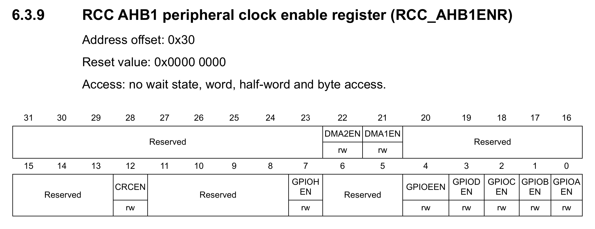
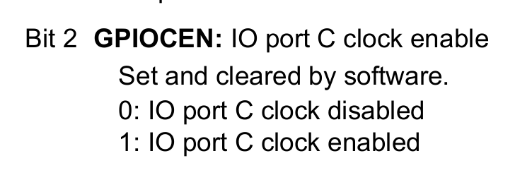
The above screenshots from refernce manual shows the bits to be written to enable clock for GPIOC.
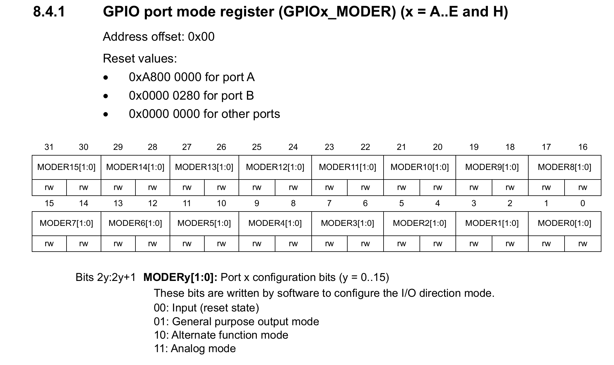
Then the GPIO port is set to general purpose output mode.
#include "stm32f401_gpio.h"

#define GPIOCEN (1U << 2) //3rd bit to enable GPIO
#define LED_PIN (1U << 13)

void led_init(void) {
    //enable clock for GPIOC
    RCC->AHB1ENR |= GPIOCEN;

    //Set led pin as output
    GPIOC->MODER |= (1U << 26);
    GPIOC->MODER &= ~(1U << 27);
}

void led_off(void) {
    //set led pin HIGH (PC13)
    //setting high turnes led off in my board
    GPIOC->ODR |= LED_PIN;
}

void led_on(void) {
    //set led pin low (PC13)
    GPIOC->ODR &= ~LED_PIN;
}

int main(void) {
    led_init();

    while(1) {
        led_on();
        for (int i = 0; i < 1000000; i++) {}
        led_off();
        for (int i = 0; i < 1000000; i++) {}
    }
}
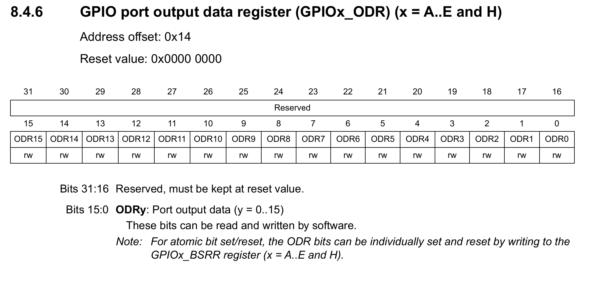
After that the led can be controlled using GPIO Output Data Register. The while loop turns the led on and off. We could have used the internal clock for timing, but to keep it simple, loop is used here.
Compiling and Uploading
For compiling this gcc-arm-none-eabi target should be installed. The Makefile compiles the code. The generated bin file must be uploaded to the microcontroller.
I used stlink software to upload the file, it will ask for the flash address to upload, for this chip it is 0x08000000.
That’s it! the led is blinking.